Fiber modulator basics: the pros and the cons of 4 intensity modulation solutions
Fiber modulator: this tutorial gives a summary of the pros and cons of the four primary technical approaches to laser intensity modulation in the nanosecond or sub-nanosecond time domain.
Three of these fiber modulator solutions are based on external modulation : AOM (Acousto-Optic Modulators), EOM (Electro-Optic Modulators), SOA (Semiconductor Optical Amplifiers) and the fourth is by directly driving the laser diode.
Full pdf version: Fiber modulator basics
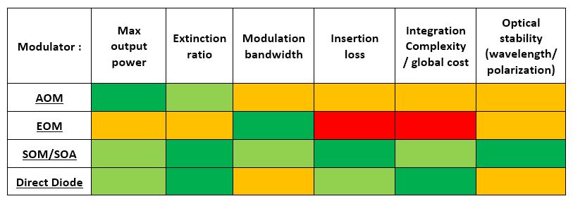
The following table gives a good overview of the outputs of this comparison:
Acousto-optics modulators (AOM)
Fiber-coupled acousto-optic devices used as fiber modulator are available at various wavelengths from 380 nm to 2500 nm. The major advantage of acousto-optic fiber coupled device modulation is the relatively high optical power these modulators can handle. They are specified to work with power levels which can reach several watts (more than 10 W in some cases). However, with acousto-optic modulators (AOM’s), a primary con is the tradeoff between the switching speed and the insertion loss. The more the optical beam is focused within the AOM’s embedded crystal, the faster it switches, but the more difficult it can reach the output fiber without suffering losses.
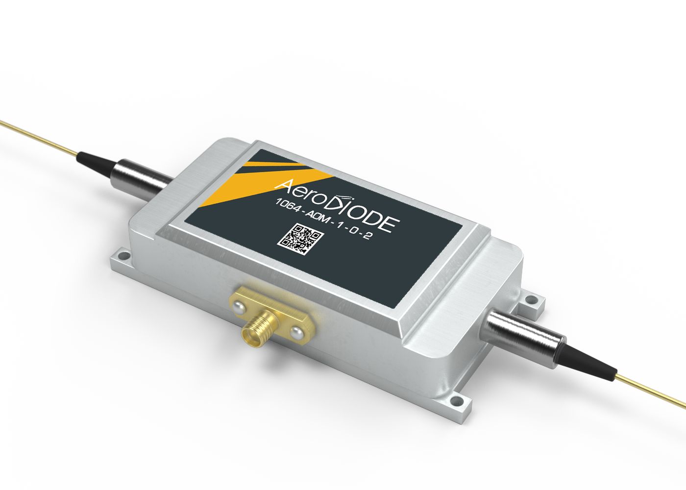
2 highly reputable manufacturers of fiber-coupled acousto-optic modulators are:
- AeroDIODE (French supplier)
- Gooch and Housego (UK supplier)
Some examples of a few models around 1064 nm and 1550 nm are given bellow:
| Wavelength (nm) | Max input power (W) | Rise time (ns) | Insertion loss (dB) |
|---|---|---|---|
| 1060 | 5 | 25 | 2.5 |
| 1060 | 0.5 | 6 | 3.5 |
| 1550 | 5 | 3 | 3.0 |
| 1550 | 1 | 6 | 3.0 |
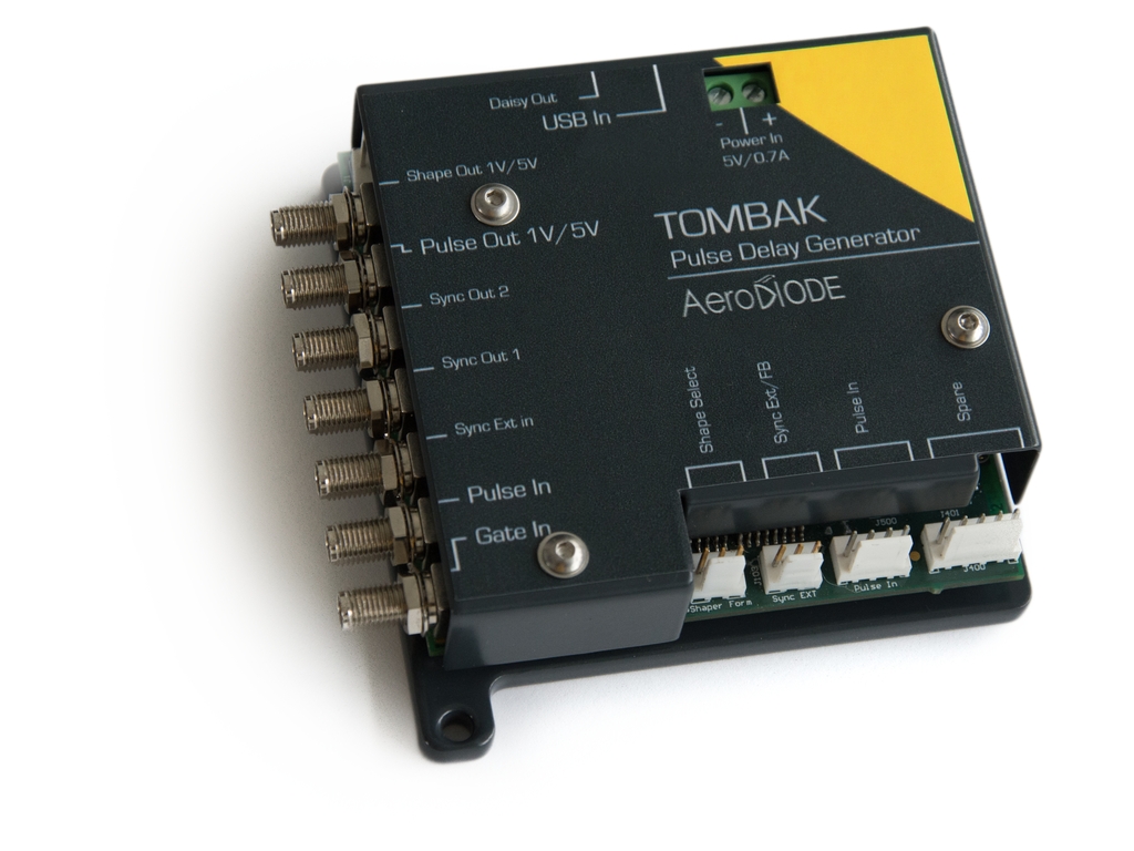
When considering the price of an AOM set-up, the user should consider the total cost of the three key elements: the component itself, the RF driver and the fast switching driving electronics generating 0-1 V or 0-5 V depending on the RF driver
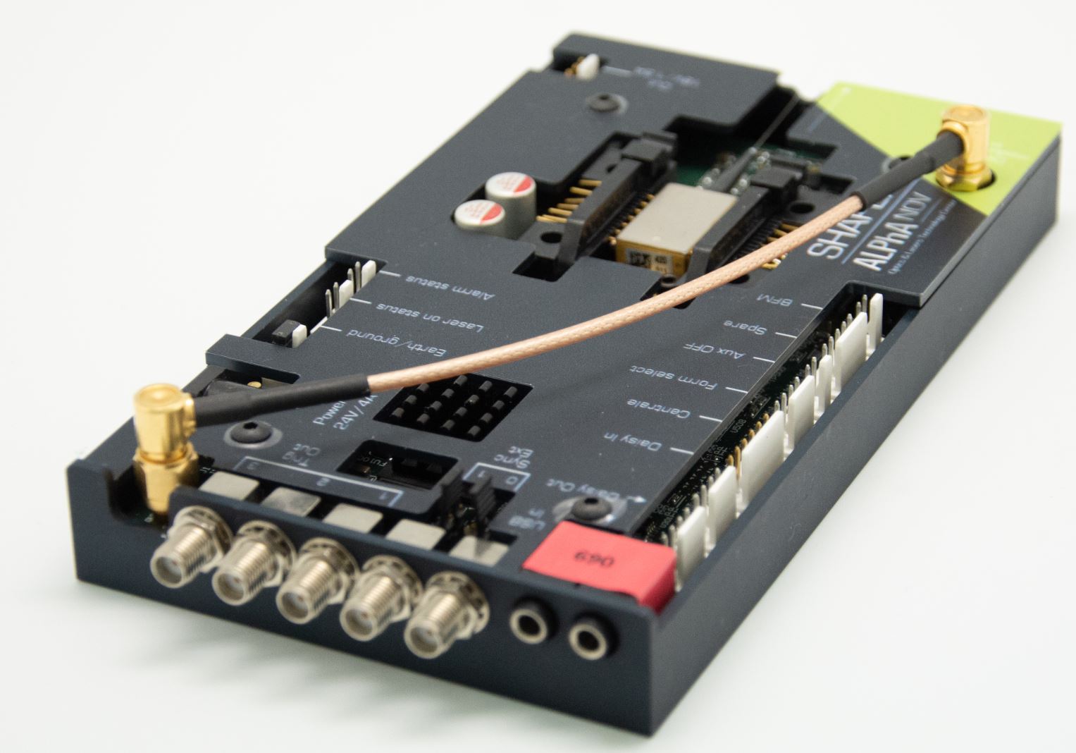
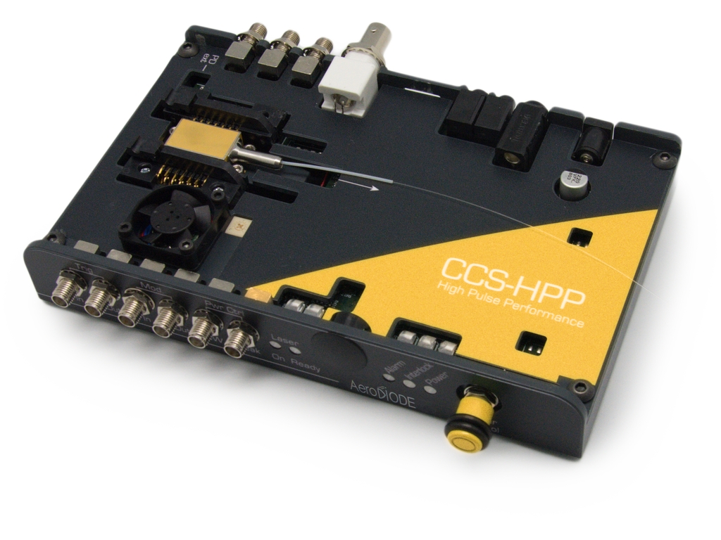
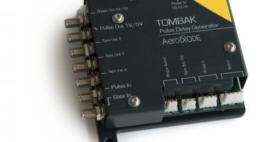
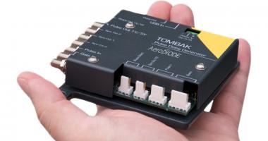
The RF driver is typically supplied by the AOM component supplier. An example of multi-function, simple to use fast switching driving electronics pulse delay generator is shown bellow. This module combines an impressive number of functions including pulse-picking and an AWG. It is manufactured by Aerodiode:
Electro-optics modulators (EOM)
The major advantage of an electro-optic modulator (EOM) is their bandwidth, which extends into the 10’s of GHz range.
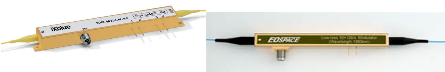
4 highly reputable manufacturers of fiber-coupled EOM electro-optics modulators are:
Several difficulties which are associated with electro-optic modulator (EOM) can be solved by increasing the complexity of the overall setup. If you decide to utilize an EOM based modulation setup, there are several parameters which need to be considered and correctly managed:
- Insertion loss levels vary from one model to another. In general, improving one key performances attribute of an EOM (ie extinction ratio) can have a negative consequence on the insertion losses. Typical insertion losses are in the range of 4-5 dB.
- Maximum input/output power: typical maximum input power is in the range of 50 mW (17 dBm). This maximum power is generally an average power. One can thus overcome this limit / problem by applying a pulsed signal at the input fiber instead of a CW signal. The modulated input signal can be generated by an AOM (refer to AOM overview above) or by directly modulating the laser diode. This, however, produces some other difficulties associated with the stability of the V-bias (see below).
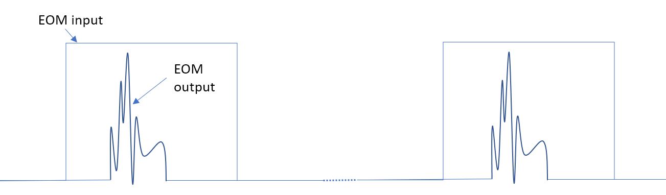
- Stability of V-bias: This is one of the most difficult technical issues to manage when using an EOM. EOM’s generally drift because of thermal inhomogeneity etc. This causes the transfer function (see Figure bellow) to move in the horizontal direction and the modulation signal is applied to a changing operating point. This can affect the quality of the modulation:
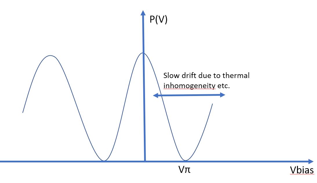
In order to operate the EOM electro-optics modulators and obtain the desired modulation, the user must apply two separate voltages to the modulator: (1) A modulation voltage V(t) and (2) a DC voltage (also called V-bias). The bias voltage selects the desired operating point and compensates for the drift in order to keep more stable operating conditions.
A typical setup for driving an EOM requires 5 types of electronics :1- laser diode driver, 2-global synchronization, 3-fast modulation, 4-RF Amplifier, 5-Vbias electronics:
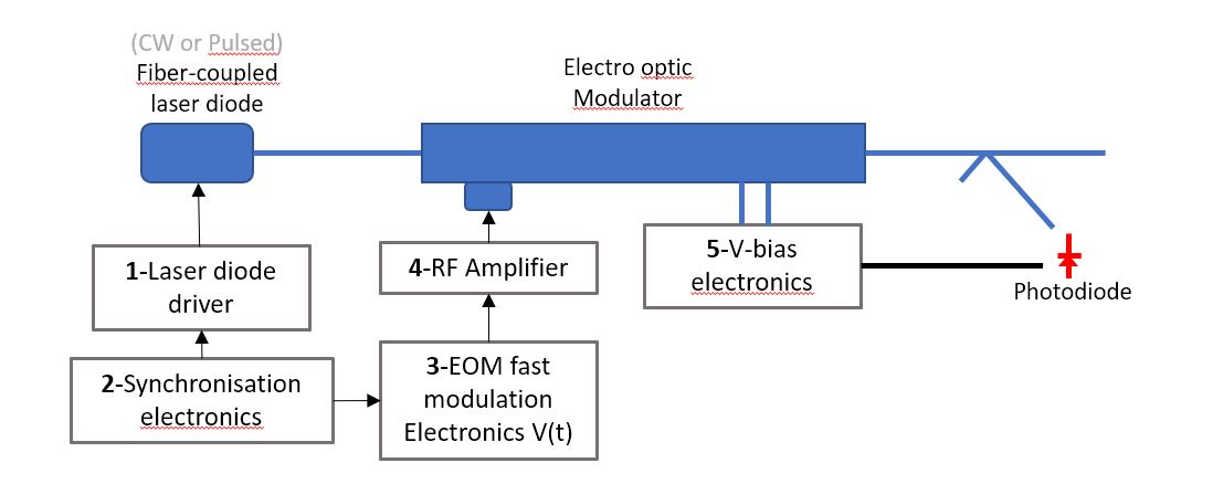
Many suppliers offer the laser diode driver described in the block diagram above. Finding a pulser which will generate stable, clean pulses in the nanosecond time domain is important. Here is an example of a well specified laser diode pulse driver:
- For the "Laser diode driver (1)": see Aerodiode pulsed laser diode driver
- For the "Synchronisation electronics (2)": see Aerodiode pulse delay generator
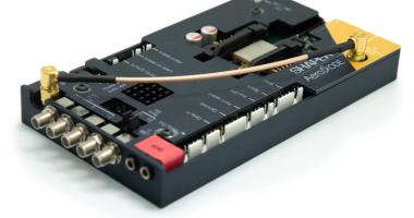
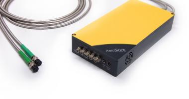
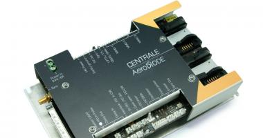
- For combining a "Laser diode driver (1)", "Synchronisation electronics (2)" and "EOM fast modulation electronics (3)", and the RF amplifier (4), a new generation pulsed laser diode driver is now proposed by Aerodiode.
This last driver is able to drive and control a butterfly laser diode, generate several synchronization signals and drive the EOM Electro Optic Modulator with a programmable pulse shape with a temporal resolution down to 500 picoseconds:
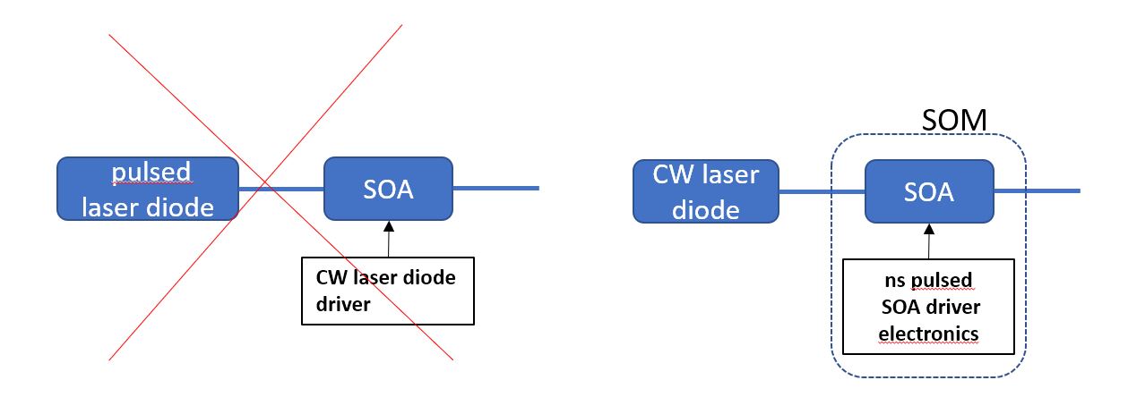
Semiconductor Optical Modulators : SOM (SOA based modulator)
SOA Semiconductor Optical Amplifiers are a well-established alternative to CW EDFA’s (Erbium Doped Fiber Amplifiers) and are used to amplify a pulsed signal. A Semiconductor optical modulator (SOM) utilizes SOA technology in a different way than traditional SOA amplifiers have been used. Semiconductor optical modulation utilizes a SOA as a fiber modulator with potentially negative insertion loss (ie Gain). In this case, a CW laser diode signal is applied to the SOA and it is the level of current driving the SOA which is switched ON/OFF at GHz speed. This modulated signal can also be customized and shaped to accommodate many emerging applications.
There is a number of advantages to use SOA fiber modulator compared with other solutions:
- The dynamic range is much higher than with EOM Electro-optic-Modulator or AOM Acousto-optic-Modulator which are most often limited due to many optical effects
- An SOM has no polarization rotation dependencies, whereas both an EOM or an AOM typically are susceptible to polarization dependencies.
- The spectrum of an SOM remains the same along the entire pulse, whereas when directly pulsing a laser diode, the user must consider the undesirable spectral effects which can occur from coupling of the frequency/phase spectrum and intensity profile.
- The SOM is the only commercially available solution which also functions as an optical isolator for the input laser source.
When using an SOM, extinction ratios as high as 70 dB are possible. The maximum input power is generally not much higher than the saturation output of typically 50 mW (17 dBm).
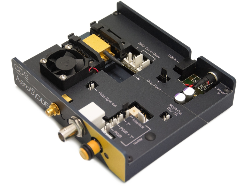
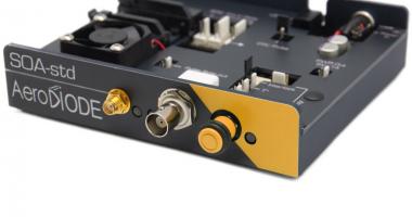
Switching the SOA current level requires a dedicated efficient and stable electronics with special functionalities to allow for very high extinction ratio up to 50 dB. AeroDIODE SOA driver is an open-frame driver and control module which is compatible with the pin configurations and the package size of most commercially available SOA’s.
AeroDIODE offers a complete SOM fiber modulator turn-key solution. This SOM is offered with a broad selection of SOA’s from 775 nm to 1625 nm. Current and temperature control circuits and safety limits are pre-set and optimized to ensure the highest level of performance in pulsed mode.
Direct laser diode modulation
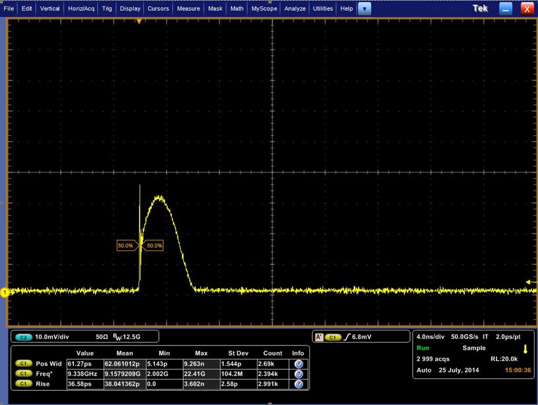
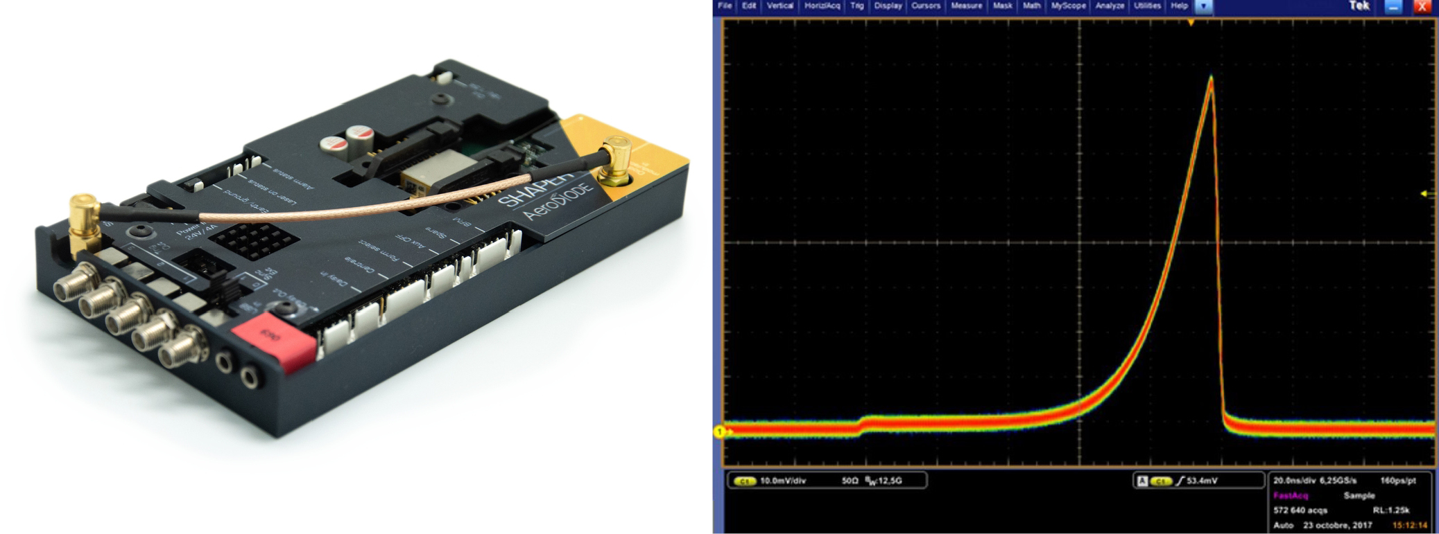
The last (but not least) solution for modulating the light coming from a fiber-coupled laser diode is to apply a direct modulation using a pulse control electronics current driver. An example of a 3 nanosecond pulse width is shown below. One can see the gain switch peak at the beginning of the pulse. This is a relaxation of the carrier within the laser diode. Gain switch peak can be useful if one wants to isolate this gain switch peak pulse and get ~ 100 picosecond pulses. But the gain switch peak is typically an undesired property.
There are fewer than 10 companies around the world who specialize in manufacturing commercially available laser diode pulse drivers. However, the pulse shape at a short pulse width and the rise/fall time and Jitter levels can be very different from manufacturer to manufacturer. Also, there are many key features and additional functions which vary from each manufacturer, and ease of use should also be considered.
The bandwidth limitations are a result of the speed of the electronics on the “drive side” and the inductance of the laser diode on the other side. Reaching a 5 nanosecond per amp rise/fall time is possible in an ON/OFF switching mode from many suppliers. However, combining modularity, ease of use and high performance levels is the most difficult part when developing a pulsed driver.
Aerodiode proposes four On/Off pulsed laser diode drivers with switching speed from 3 ns/A to less than 0.5 ns/A:
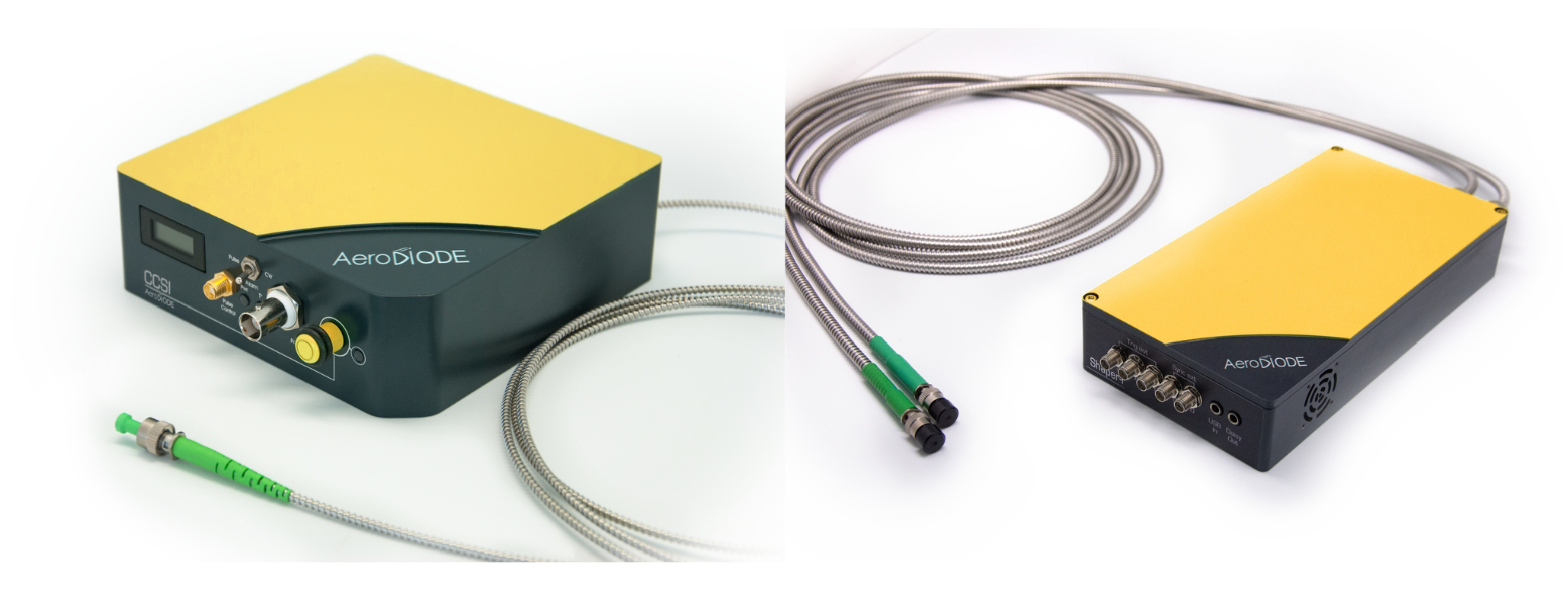
Another high performance product for direct laser diode modulation is called a pulse shaper. It includes an internal AWG and is able to shape the laser diode output with 48 dB amplitude resolution and 500 picosecond timing resolution:
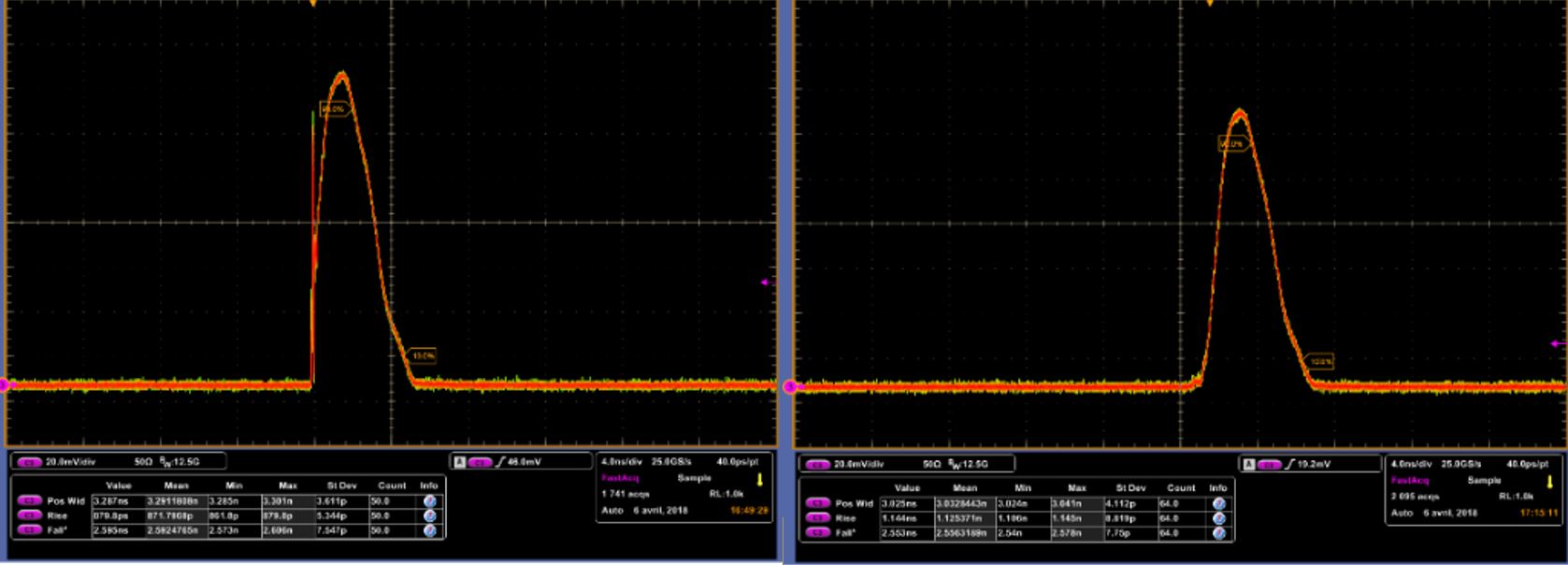
This pulse shaper module allows the user to program a customized shape with a high bandwidth AWG and generates the desired custom optical pulse shaper. As seen in the figure bellow, this module also has a special internal function which allows the user to mitigate the gain switch peak:
Conclusion
The table below summarizes the pros and the cons of the various fiber modulator solutions. AOMs are interesting when looking for several Watts of output power. EOMs are the fastest solutions despite a high level of integration complexity and low extinction ratio. SOM (i.e. SOA Semiconductor Optical Amplifiers used in a fiber modulator configuration with a special electronics) has clearly major advantages when looking for a cost-effective GHz speed solution. Direct laser diode is the cheapest solution but be careful that the wavelength will shift all along the pulse and one needs to choose the good driving electronics to reach a correct peak power when looking for less than 10ns pulse width and eventually avoiding the gain switch peak.
Associated products or services
-
Pulsed laser diode driver & TEC control
This pulsed laser diode driver with high speed performances and integrated TEC controller generates any pulsed or CW optical signal from 1 nanosecond to CW. -
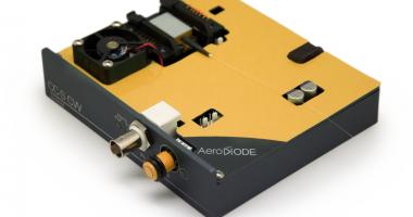
Laser driver with TEC control & USB: CCS-CW
This laser driver generates CW and modulated optical signal from a butterfly laser diode or any other form-factor . It is USB controlled with a GUI and several libraries are available for system integration (Labview, DLLs, Python, Hexa etc.). It is also available at board level for OEM integration. -
High speed laser diode driver with user design nanosecond pulse shape
This pulsed laser diode driver generates any pulsed shape with down to 500 ps step and 48 dB dynamic range. -
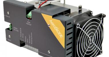
High power laser diode driver up to 36 V - 21 A with TEC & air cooling
This high power laser diode driver is able to drive in CW or pulse regime, multimode fiber laser diodes. -
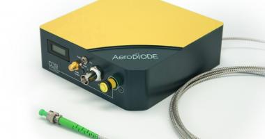
Turn-key laser diode module with DFB or Bragg sources at any wavelengths
This laser diode module generates any pulsed or CW optical signal from an integrated semiconductor DFB or Bragg sources at various visible or infrared wavelengths. It is a low noise high peak power laser diode source with USB and control electronics for pulse width down to 1 ns. -
Pulse delay generator ideal for timing and synchronization
This pulse delay generator generates high frequency pulses, digital delays and bursts. It is an ideal synchronization and timing control instrument for electronics and lasers. -

Pulse Picker synchronization board – up to 200 MHz input / 20 MHz output
A synchronization tool to drive external modulating devices like EOM, AOM, SOA for optical pulse picking. It’s adjustable threshold makes it compatible with low input signal levels. Several pulse picking modes and several output voltage levels. LabVIEW, DLLs, Hexa, Python libraries -
Fiber modulator: a high speed intensity modulator and optical switch
This fiber modulator is a lossless, low noise, high speed (~ns), high dynamic range, high extinction ratio solution available from 750 to 1700 nm. -
SOA pulsed driver with nanosecond speed: a new fiber modulator
SOA pulsed driver with nanosecond speed: a new alternative to AOM and EOM fiber intensity modulation. -
1064 nm laser diode – CW & pulsed – Bragg or DFB
These 3 version of fiber coupled 106 4nm laser diodes are offered as stock items or associated with a CW or pulsed laser diode driver. -
Digital Delay Generator - 10 ps resolution - 15 ns insertion delay - 30 mV min input
This Digital Delay Generator is an ideal tool for timing and gating of optoelectronics instruments such as cameras or lasers. -
Fiber laser diode driver - pulse and CW - and many other functionalities
This fiber laser diode driver is like a “motherboard” for fiber laser R&D and product development. It integrates 2 CW and pulsed laser diode drivers, 6 photodiode electronics, a pulse-picker synchronization tool and many other dedicated functionalities for every type of fiber laser architecture. -
Multi-channel laser diode driver – CW or Pulsed – up to 8 channels
This laser diode driver & temperature controller allows full independent control of up to 8 laser diodes from CW down to very short pulses. It includes several functions including a pulse generator and a very low noise current and modulation driver. -

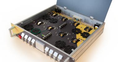
Reliability test system for laser diode qualification in pulsed or CW regime
Life-test and qualification test system for laser diode reliability evaluation in CW or pulsed regime down to 1 nanosecond. Up to 112 fully independent fibered devices are electrically, thermally and optically tested according to one or several user-programmed test scenarios.


